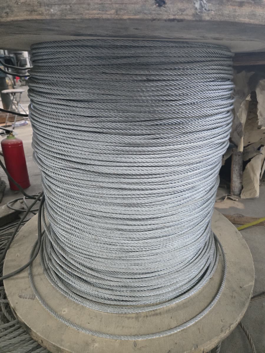
Load path
Galvanised load cable
6×19W+IWR-1870 B Z construction, galvanised against moisture. Diameter is set per project — typically Φ18 mm — from the span, the sag and the rider load.
A zipline fails at its weakest component, so none of them are afterthoughts. This is the hardware that ships with each system and what each piece is doing.
The three parts that carry and stop a rider. Everything else exists to hold them in place.
6×19W+IWR-1870 B Z construction, galvanised against moisture. Diameter is set per project — typically Φ18 mm — from the span, the sag and the rider load.
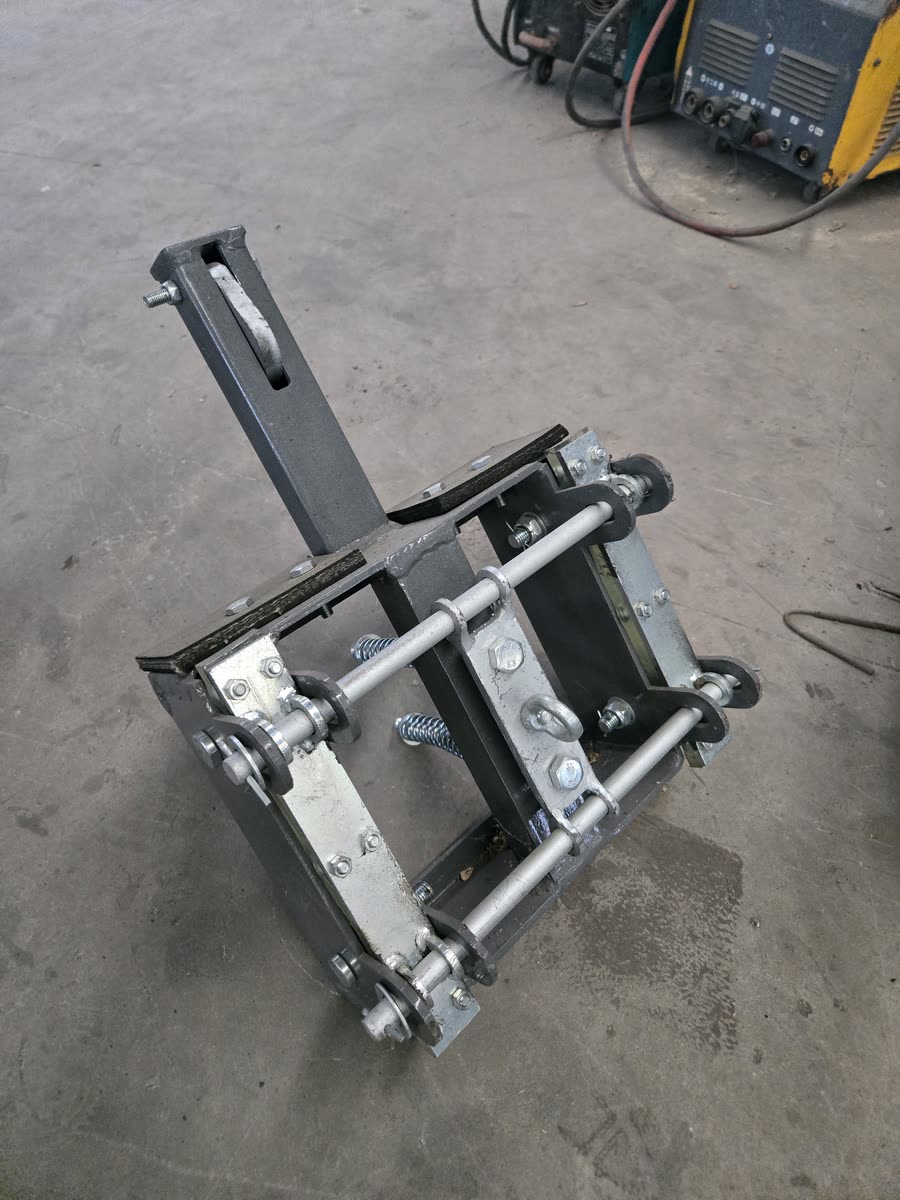
Spring-loaded rubber brake that absorbs the rider's kinetic energy over a controlled distance, bringing the trolley to a stop before the buffer rather than at it.
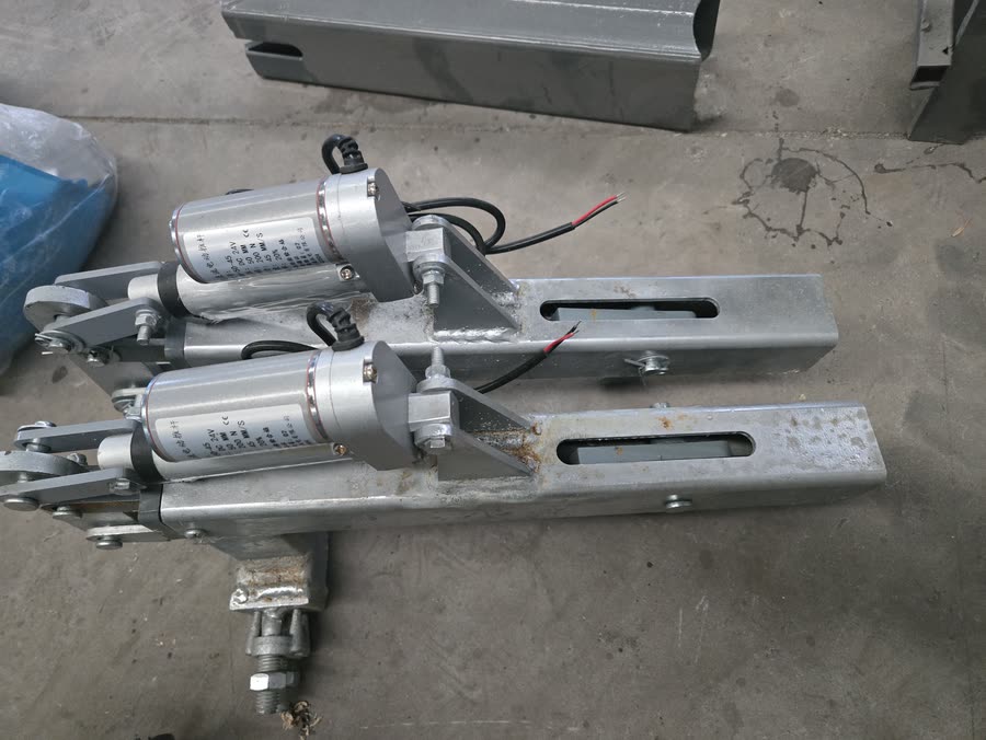
Holds the trolley at the upper station until the operator releases it. One deliberate action per launch, so a rider cannot be sent by accident.
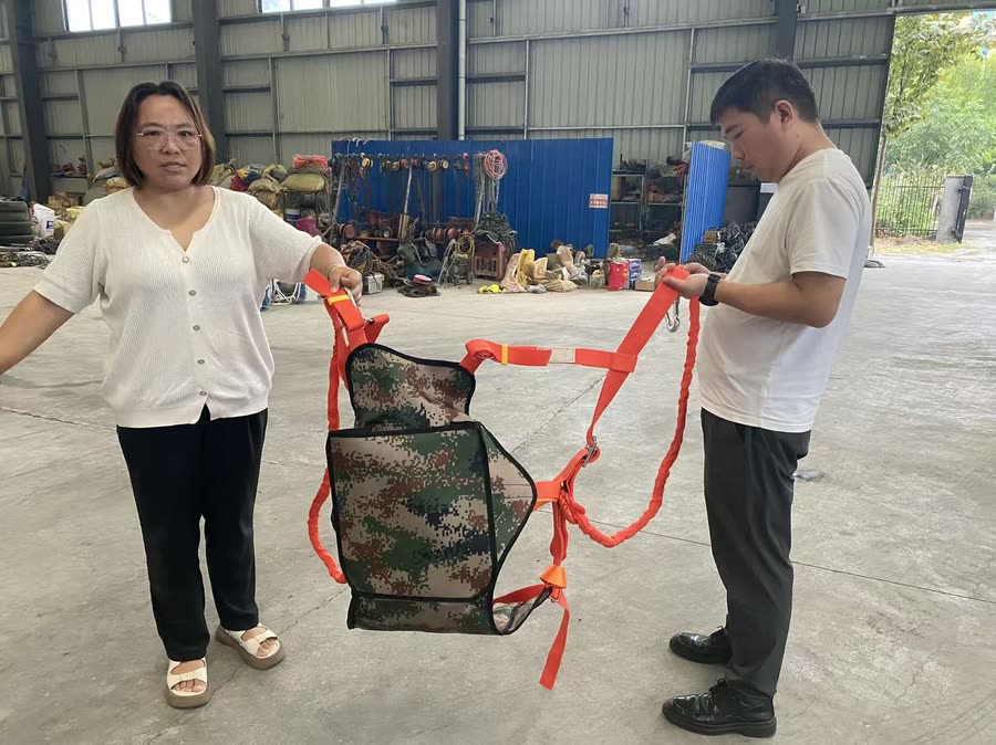
Multi-point harness with seat sling, one set per trolley. Chest, waist and leg attachment so the load is spread across the body, not carried at the waist alone.
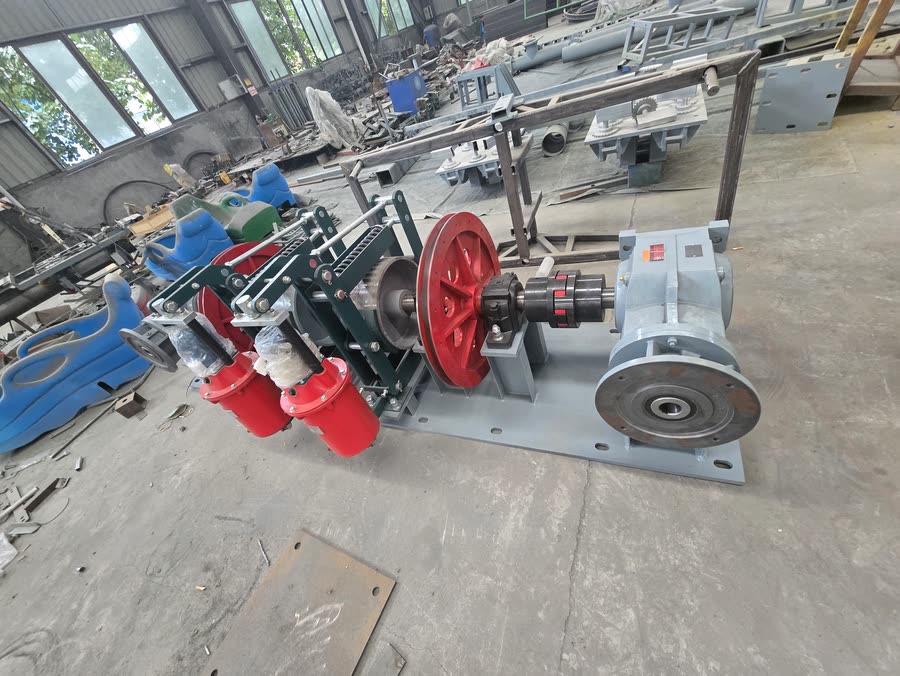
Returns trolleys from the lower station to the top, and doubles as the drive for recovering a rider who stops mid-line. Manual or electric drive.
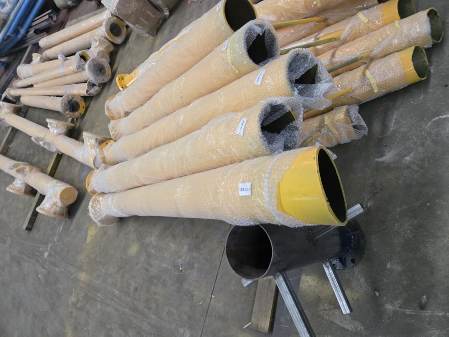
Φ216 mm circular tube, hot-dip galvanised after fabrication so the coating covers welds and cut ends, not just the outside faces.
No amusement ride can be described as risk-free, and any supplier who says otherwise is telling you something about how they think. What a well-built zipline does is make sure no single failure takes a rider down.
Standard set for a twin-line installation. Quantities scale with the number of lines ordered.
| Upper station tower | Φ216 circular tube, galvanised — 1 per station |
|---|---|
| Lower station tower | Φ216 circular tube, galvanised — 1 per station |
| Load cable | 6×19W+IWR-1870 B Z — cut to span length |
| Anchor safety cables | Independent secondary cable, upper and lower |
| Trolleys | 2 per line, standard set of 10 |
| Harnesses | Full-body with seat sling, 1 per trolley |
| Rubber deceleration unit | 1 per line |
| Buffer stop | 1 per line |
| Anti-collision frame + sponge pad | 1 per line |
| Recovery winch & trolley | 1 recovery system per installation |
| Rescue trolley | Supplied with the recovery system |
| Anemometer | 1 per station |
| Cable clamps, shackles, turnbuckles | Full fixing set, matched to cable diameter |
| Release hook | 1 per line |
Civil works, station buildings, access roads, perimeter fencing and local electrical supply are by the client. Foundation drawings are supplied with the order.
Tell us your span and line count and we send the itemised scope of supply with the quotation — not a single lump-sum figure.